Wiring A Switched Outlet With 3 Wire, 3 Way Switch Wiring Electrical 101
Wiring a switched outlet with 3 wire Indeed lately has been sought by consumers around us, perhaps one of you personally. Individuals are now accustomed to using the internet in gadgets to see image and video information for inspiration, and according to the title of the post I will discuss about Wiring A Switched Outlet With 3 Wire.
- Wiring Diagram For Two Switches To Control One Receptacle Light Switch Wiring Wire Switch Electrical Wiring
- Eaton Wiring Tr274v 3 Wire Receptacle Combo Single Pole Switch With Tamper Resistant 2 Pole Ivory Electrical Outlet Switches Amazon Com
- Wiring Diagrams
- Wiring Diagrams For Switched Wall Outlets Do It Yourself Help Com
- How To Wire A Split Receptacle
- How To Wire A Light Switch And Outlet In The Same Box Quora
Find, Read, And Discover Wiring A Switched Outlet With 3 Wire, Such Us:
- How To Wire Gfci Combo Switch Outlet Gfci Switch Outlet Wiring
- About Switched Outlets Electrical Online
- Wiring Diagrams For Switched Wall Outlets Do It Yourself Help Com
- Wiring Diagrams To Add A New Light Fixture 3 Way Switch Wiring Light Switch Wiring Wire Switch
- Wiring A Switched Outlet Wiring Diagram Electrical Online
If you re searching for Camelback Inn Thanksgiving Dinner 2019 you've arrived at the right location. We have 104 graphics about camelback inn thanksgiving dinner 2019 adding images, pictures, photos, wallpapers, and more. In these webpage, we additionally provide number of graphics out there. Such as png, jpg, animated gifs, pic art, symbol, blackandwhite, translucent, etc.

Pin On Wiring Camelback Inn Thanksgiving Dinner 2019

Installing A Switched Receptacle Better Homes Gardens Camelback Inn Thanksgiving Dinner 2019
How To Wire An Outlet To A Switch Half Hot Receptacle Youtube Camelback Inn Thanksgiving Dinner 2019
Wiring Diagrams Double Gang Box Do It Yourself Help Com Camelback Inn Thanksgiving Dinner 2019
How To Wire A Light Switch And Outlet In The Same Box Quora Camelback Inn Thanksgiving Dinner 2019
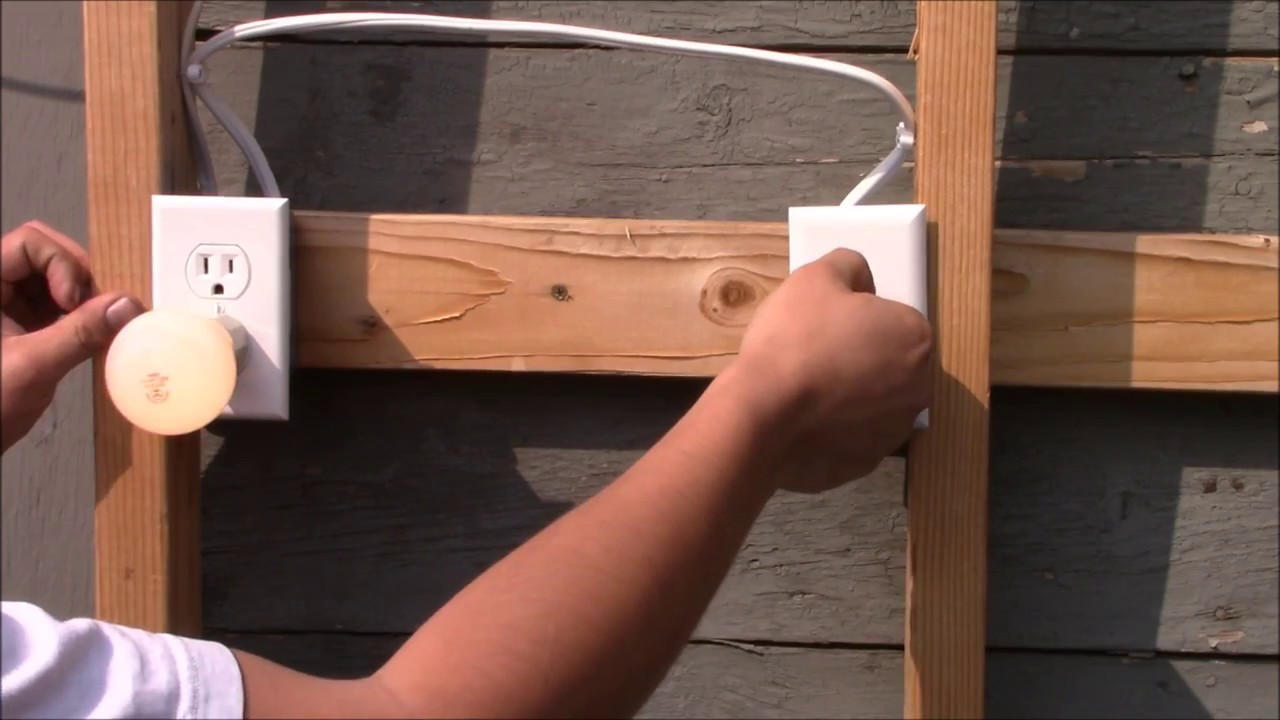
How To Wire A Switched Outlet Youtube Camelback Inn Thanksgiving Dinner 2019
Fan light bulb etc.
Camelback inn thanksgiving dinner 2019. Connect the last switch in the usual manner looping the wire around the screw in a clockwise direction. Three wire cable runs from the switch to the outlet providing two hot wires to that location. Instead of running a separate pigtail from the hot wire to each switch just leave the hot wire extra long.
Pull 123 or 143 romex with ground cable from the switch controlled receptacle box to the switch box. At the receptacle the red connects to the top half of the outlet. If its a yellow wire nut youll be pushing its capacity limits so maybe change it for a red wire nut.
To do this simple remove the breakaway fin between the line terminals and connect the upper terminal to source one and the lower line terminal to source two. However each outlet and switch is required to have its green screw connected to a grounding conductor. How to install electrical outlet and switch combo wiring in most cases the primary power source is shared between the switch and the outlet either with a wire jumper or the bridge or tab that is located on the side of the combo switch and outlet.
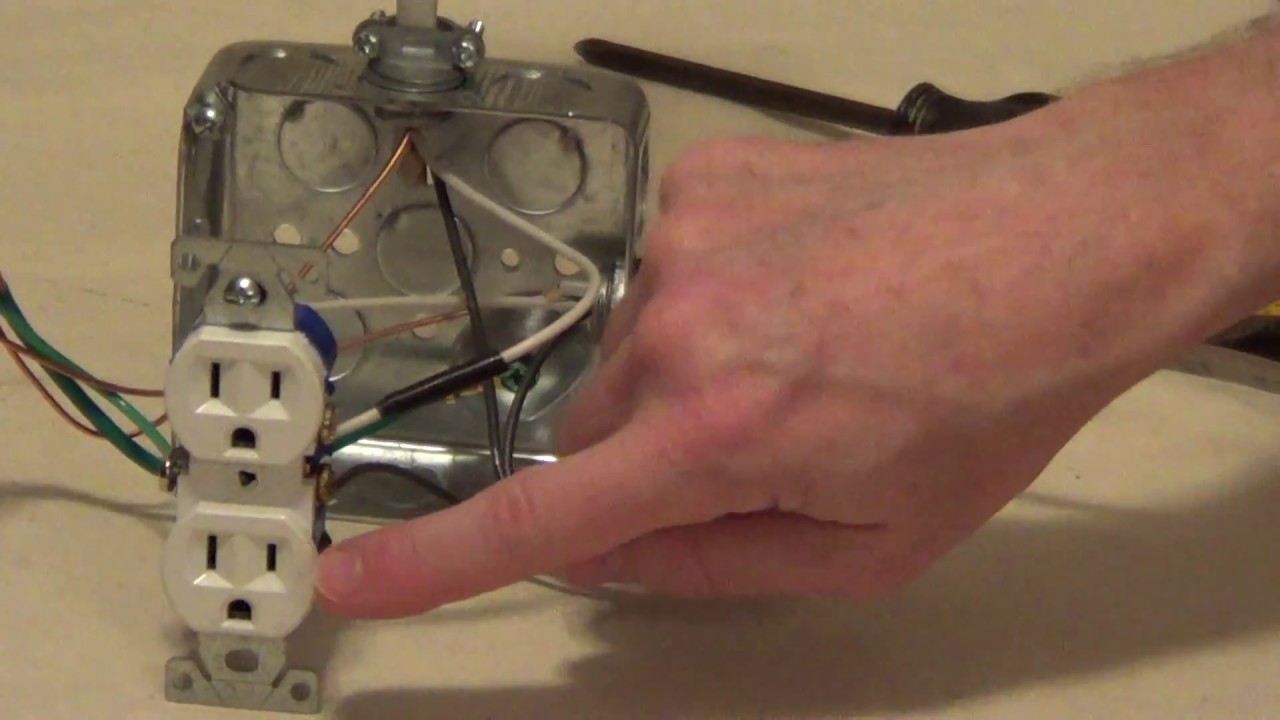
Attach the black and the white wires to the receptacle by placing their loops under the brass and silvered colored screws in a clockwise direction and tightening the screws down on the wire. The neutral wire from the circuit is shared by both sets. The required grounding conductor is not shown in order to keep the diagrams simple.
Here 3 wire cable is run from a double pole circuit breaker providing an independent 120 volts to two sets of multiple outlets. The neutral is connected from the main breaker to all outlets neutral terminal. Ground wire is connected to the outlets as well as shown in the fig.
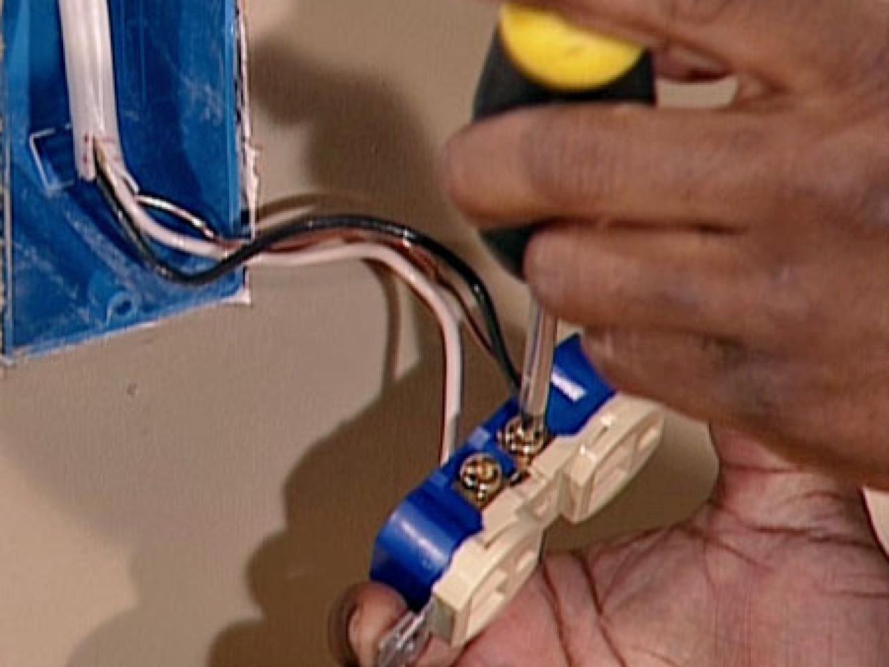
To connect the switches simply score the wire with your wire stripper and push the insulation to expose about 34 in. The black cable wire runs from the switch to the bottom half of the outlet. Electrical wiring for a switch outlet combination.
Now attach the pigtail to the other brass screw on that receptacle. Add the pigtail to the 3 wires on the wire nut. The source hot at the switch is spliced with the red cable wire to the outlet and a pigtail to the switch.
Wiring a combo switch outlet. In this wiring the first and 3rd outlet hot terminals are connected to the line 2 blue and the second and last outlets hot terminals are connected to the line 1 red. The neutral wire from the circuit is shared by both sets.
The lower neutral should be connected to the source two neutral wire and the switch load should be connected to the load point ie.
How To Wire A Switched Outlet This Is Post 3 Of 3 In Our Series By Rising Barn Medium Camelback Inn Thanksgiving Dinner 2019
3 Camelback Inn Thanksgiving Dinner 2019
Replacing Outlets How Tos Diy Camelback Inn Thanksgiving Dinner 2019
Wiring Diagrams For Switched Wall Outlets Do It Yourself Help Com Camelback Inn Thanksgiving Dinner 2019
More From Camelback Inn Thanksgiving Dinner 2019
- Gambar Naruto Duduk Di Ayunan
- Giant Turkey 2020 Meme
- Pappas Barbecue Thanksgiving Menu
- Kfc Coupons
- When Does Tj Maxx Open On Black Friday
Incoming Search Terms:
- House Electrical Wiring Connection Diagrams When Does Tj Maxx Open On Black Friday,
- How To Replace A Light Switch With A Switch Outlet Combo When Does Tj Maxx Open On Black Friday,
- How To Wire A Switched Outlet Youtube When Does Tj Maxx Open On Black Friday,
- Light Switch Wiring Diagrams Do It Yourself Help Com When Does Tj Maxx Open On Black Friday,
- Wiring Diagrams For Switched Wall Outlets Do It Yourself Help Com When Does Tj Maxx Open On Black Friday,
- Outlet With 3 Sets Of Wires Home Improvement Stack Exchange When Does Tj Maxx Open On Black Friday,